

 en
en Español
 русский
 中文简体
中文简体
Industry News
Troubleshooting Hydraulic Elevator Power Units: Pumps, Mufflers, and Oil Coolers
Content
- 1 Understanding the Core Architecture of Hydraulic Power Units
- 2 Elevator Hydraulic Pump Diagnostics and Failure Modes
- 3 Troubleshooting Hydraulic Pump Mufflers and Acoustic Anomalies
- 4 Thermal Management: Optimizing Hydraulic Oil Temperature Control
- 5 Elevator Valve Block Adjustment and Interface Mechanics
- 6 Frequently Asked Questions
- 6.0.1 Q1: Why is the hydraulic elevator making a loud rattling sound during upward travel?
- 6.0.2 Q2: How often should the cooling core of pit oil coolers be cleaned?
- 6.0.3 Q3: What causes an elevator submersible pump to overheat when traffic is normal?
- 6.0.4 Q4: Can a faulty scavenger pump elevator system cause ride quality issues?
- 6.0.5 Q5: How can you tell if an elevator valve block needs new seals?
Understanding the Core Architecture of Hydraulic Power Units
Hydraulic elevator power units serve as the mechanical heart of vertical transportation systems in low-rise commercial structures and residential applications. The unit houses the primary components responsible for fluid displacement, pressure regulation, and thermal management. Ensuring the seamless operation of these assemblies requires a comprehensive understanding of how sub-components interact under fluctuating load conditions.
A standard hydraulic lift tank unit comprises a fluid reservoir, a high-pressure pump, an electric motor, a control valve manifold, and auxiliary conditioning systems such as oil coolers and noise suppression mufflers. When a call is registered, the motor drives the pump to displace hydraulic fluid from the reservoir through the control valve block and into the jack assembly, elevating the cab. During descent, gravity forces fluid back into the tank, regulated precisely by the valve network.
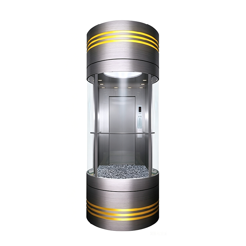
System reliability depends heavily on maintaining fluid integrity and system pressure. For specialized installations, including a modern panoramic elevator or a multi-level home elevator, space constraints within the machine room or pit alter the thermal dissipation rates and acoustic profiles of the machinery. Consequently, troubleshooting must be approached with a holistic view of the structural environment and operational duty cycles.
Elevator Hydraulic Pump Diagnostics and Failure Modes
The elevator hydraulic pump is the core mechanism executing fluid transfer. In most contemporary designs, an elevator submersible pump configuration is used, where the pump and motor are entirely submerged within the hydraulic oil reservoir. This setup leverages the oil for natural sound attenuation and thermal cooling of the motor windings. However, when diagnostic issues arise, encapsulation makes immediate visual inspection impossible.
Cavitation vs. Aeration
A primary failure mode in hydraulic pumps is mechanical noise generated by fluid voids. Technicians frequently misdiagnose the root cause, leading to ineffective component replacement. It is vital to differentiate between cavitation and aeration:
- Cavitation: This occurs when the pump demands more fluid than the inlet line can supply. High vacuum levels cause vapor bubbles to form within the hydraulic oil. As these bubbles enter the high-pressure zone of the pump, they collapse violently. This creates localized shockwaves, erodes internal metal surfaces, and produces a distinct, high-pitched metallic crackling sound.
- Aeration: This happens when outside air enters the fluid stream on the intake side of the pump. Air bubbles do not collapse like vapor bubbles; instead, they compress and expand, resulting in a spongy ride quality, erratic elevator leveling at floors, and a consistent whining sound from the tank unit.
To diagnose pump issues efficiently, technicians should monitor system pressure and acoustic variations across standard operation cycles. The table below lists typical pump symptoms along with their mechanical root causes and corrective steps.
| Observed Symptom | Potential Root Cause | Diagnostic Verification | Corrective Action |
|---|---|---|---|
| High-pitched metallic crackling | Inlet Cavitation | Check inlet strainer for debris or high oil viscosity. | Clean/replace strainer; verify oil grade matches ambient room temperatures. |
| Erratic leveling and foamy oil | System Aeration | Inspect fluid level and low-pressure suction seals. | Replenish hydraulic oil; tighten all loose suction-line fittings. |
| Slow travel under full load | Internal Volumetric Slip | Perform a timed pressure test against a closed isolation valve. | Rebuild pump internal rotating group or replace worn gears/screws. |
| Motor hum without rotation | Mechanical Seizure or Phase Loss | Measure electrical current draw across all three power phases. | Check supply voltage contactors; verify free rotation of pump shaft. |
In high-traffic installations utilizing a scavenger pump elevator setup, additional care must be given to auxiliary fluid recovery. The scavenger system collects residual oil weeping past cylinder packings and pumps it back to the main reservoir. If the scavenger pump fails, fluid accumulates in the pit, causing potential environmental compliance issues and risking contamination of the main hydraulic system if back-siphoning occurs.
Troubleshooting Hydraulic Pump Mufflers and Acoustic Anomalies
Acoustic performance is critical in premium passenger lift systems. Hydraulic pump mufflers are installed inline between the control valve block and the main discharge line to isolate and dissipate fluid pulsations before they reach the architectural structure of the building. Without effective silencing, high-frequency pressure waves travel along the pipe network, transforming into an audible drone inside the elevator cabin or adjacent building spaces.
Structural Integrity of Silencing Mufflers
A typical silencing muffler for lift pump assemblies uses gas-charged bladders or multi-chamber internal baffles to break up pressure ripples. Over thousands of operational cycles, these components can degrade. Gas-charged bladders lose their pre-charge pressure, while internal baffles can suffer weld fatigue due to constant pressure fluctuations. When a muffler fails internally, it can either restrict oil flow entirely or lose its acoustic attenuation properties.
When troubleshooting acoustic issues, distinguish between structural resonance and fluid-borne noise. If vibrations occur only when the pump starts or stops, the issue usually stems from hard-conduit routing or failing vibration isolation pads beneath the tank unit. Conversely, a continuous pulsing drone during the up-travel phase indicates a failing or improperly sized hydraulic pump muffler.
Verifying Muffler Integrity
To verify the integrity of an inline muffler, technicians can use dual-point surface temperature measurements and acoustic comparison checks:
- Measure the surface temperature at both the inlet neck and the discharge body of the muffler during heavy use. A significant temperature drop across the device indicates an internal restriction or a collapsed baffle that is converting pressure energy into localized heat.
- Use an industrial stethoscope placed directly on the muffler shell. If fluid pulsations pass through to the downstream piping without a noticeable drop in decibel levels, the internal acoustic dampening mechanism is compromised.
- Inspect the external shell for micro-fissures or weeping oil. High-pressure fatigue can compromise structural welds, presenting a serious safety risk under peak working pressures.
Thermal Management: Optimizing Hydraulic Oil Temperature Control
Maintaining the correct operating temperature of hydraulic oil is essential for system longevity and floor-leveling accuracy. The optimal temperature range for standard hydraulic fluid is between 30 and 50 degrees Celsius. When temperatures exceed 60 degrees, the oil's viscosity drops sharply, leading to internal component wear, accelerated seal breakdown, and inconsistent valve performance.
High-duty-cycle installations require dedicated hydraulic oil temperature control hardware. Air-to-oil heat exchangers, such as a standalone mei oil cooler loop, are commonly integrated into the main tank system. These units use a small dedicated motor to draw hot oil from the reservoir, pass it through an aluminum cooling core, and return it at a lower temperature. An oil cooler with pump assembly ensures constant fluid circulation regardless of whether the main elevator motor is running.
In setups with significant space limits, like pit oil coolers placed directly in the hoistway pit, maintaining air circulation around the cooling core is essential. If trash or dust collects around the pit-mounted core, thermal dissipation stops, leading to overheating even if the cooler's fan works correctly.
System Overheating Troubleshooting Workflow
When investigating persistent overheating issues, follow this structured diagnosis process:
- Verify Thermal Sensor Calibration: Use an independent infrared thermometer to check the accuracy of the tank's built-in digital thermostat. Faulty sensors can trigger false overheat errors or fail to activate the cooling loop.
- Inspect the Cooling Core: Check for dust buildup or bent aluminum fins on the heat exchanger. Clean the core with low-pressure compressed air or an industrial fin comb if necessary.
- Check Circulation Pump Rotation: Verify that the auxiliary motor on the oil cooler with pump is turning in the correct direction. A reversed phase connection will significantly reduce fluid flow through the heat exchanger core.
- Analyze Valve Bypass Times: Excess heat is often caused by mechanical issues rather than cooling system faults. If the elevator valve block is worn or out of adjustment, fluid can bypass back to the tank under high pressure during the up-cycle, creating substantial heat.
Elevator Valve Block Adjustment and Interface Mechanics
The elevator valve block regulates fluid flow into and out of the cylinder jack. It uses a series of adjustable solenoid valves and mechanical pistons to manage acceleration, high-speed travel, deceleration, and leveling speeds. If a valve is improperly calibrated or contains debris, the elevator may experience jerky transitions, rough stops, or fail to move entirely.
When working on the valve block, make adjustments incrementally. Small adjustments to a bypass or acceleration screw can significantly impact car speed and leveling precision. The list below outlines the primary adjustment parameters found on industrial control valve blocks:
- Up Acceleration: Controls how quickly the fluid reaches full flow when the pump starts. If set too tight, passengers will feel a sudden jerk during start-up. If too loose, the motor may run too long before the car moves, generating excess heat.
- Down Deceleration: Determines the transition from high speed to leveling speed during descent. Worn seals inside this chamber can cause the elevator to overshoot the floor landing zone.
- Bypass Valve: Directs oil back to the reservoir until the motor reaches its full operating speed. If this valve fails to close completely, the car will travel slowly or fail to carry its rated capacity.
Regular maintenance should include checking the electrical solenoids on the valve block. Measure coil resistance with a digital multimeter; an open circuit or shorted winding will prevent the internal plunger from shifting, disabling that specific speed or direction control pathway.
Frequently Asked Questions
Q1: Why is the hydraulic elevator making a loud rattling sound during upward travel?
A loud rattling sound usually points to cavitation within the main pump or an internal failure in the inline hydraulic pump mufflers. Check that the oil level is correct and verify that the suction strainer is clean. If the noise continues after cleaning, inspect the silencing muffler for lift pump assemblies to ensure internal components haven't collapsed.
Q2: How often should the cooling core of pit oil coolers be cleaned?
Pit oil coolers should be inspected and cleaned every six months. Because they are located in the elevator hoistway pit, they easily collect dust, lint, and debris. This buildup blocks airflow and reduces thermal dissipation efficiency.
Q3: What causes an elevator submersible pump to overheat when traffic is normal?
Overheating under normal traffic conditions is typically caused by a failing oil cooler with pump assembly, a blocked heat exchanger core, or an improperly adjusted elevator valve block that is bypassing fluid under high pressure back into the tank unit.
Q4: Can a faulty scavenger pump elevator system cause ride quality issues?
A scavenger pump system does not directly alter ride quality, as its main job is to pump overflow oil back to the tank. However, if it fails and allows the pit to flood, it can lead to environmental issues or allow water and dirt to contaminate the main hydraulic oil supply over time.
Q5: How can you tell if an elevator valve block needs new seals?
Signs of worn valve block seals include floor drifting when the car is parked, jerky transitions during deceleration, and a noticeable drop in speed when carrying a full load due to internal fluid bypass.
Related Products
Related News
Built on safety, forging trust in vertical mobility.
lf you have any questions or need help, feel free to contact with our team.
 export@tenau.com.cn
 +86-18601458867
 +86-512-65059883
Elevator & Escalator
Factory Add
East of Xicheng Road, North of Lianyi Road, Nanxun Economic Development Zone, Nanxun District, Huzhou City, Zhejiang Province, P.R.China
Copyright © Tenau Elevator (China) Co., Ltd. All Rightd Reserved.
Custom High Quality Elevator Suppliers and World Brand Elevator Company